
Loaned to TNMoC by Birmingham Museums Trust on behalf of Birmingham City Council, the Harwell Dekatron computer, also known as WITCH, first ran in 1951 and by great fortune still exists today. It was restored to full working order in 2012, in association with the CCS (Computer Conservation Society) and can now be seen in the First Generation Gallery at TNMOC.
The history of the Harwell Dekatron is fascinating. In 1951 it was one of only a handful of computers in the world, and by 1973 it was acclaimed the world's most durable computer. Now that restoration is complete it is the oldest original working digital computer in the world - a record that is likely to stand for as long as it continues to function.
Between late 2009 and 2012, a TNMOC team of volunteers used its ingenuity and re-engineering skills to restore this record-breaking computer. The machine was rebooted on 20 November 2012 in the presence of two of the original designers and two former users.
The story behind the Harwell Dekatron / WITCH computer is an enthralling one. It has led a charmed life and on three occasions has been brought back from the brink of destruction.
Design of the computer began in 1949 at Harwell where there was a pressing need to automate the calculations then being performed on hand calculators by human "computors" (as they were then known). Construction was completed in 1952 when it was passed to the mathematicians to exploit its reliability -- when required it ran for more than 90 hours a week in its first year, although its speed of performance was that of a tortoise rather than a hare.
By 1957 it was becoming obsolete at Harwell and was offered in a competition to an educational establishment proposing its most appropriate use. It was won by the Wolverhampton and Staffordshire College of Technology who used it as the Wolverhampton Instrument for the Teaching of Computation from Harwell (hence its later name, the WITCH).
In 1973, it was recognised by the Guinness Book of Records as "the world's most durable computer" and was acquired by Birmingham City Council for display at the Birmingham Museum of Science and Industry. When that Museum closed in 1997, it was put into storage, but following TNMOC’s successful proposal to restore it to working order, a long-term loan was agreed, and it moved to TNMOC for restoration in 2009.
Restoration was completed in November 2012 and and in 2013 it was again recognised by Guinness World Records, this time as the world's oldest original working digital computer. Today it is one of the Museum's most popular exhibits.

Restoration
Project Aims
In the restoration of the Harwell Dekatron / WITCH computer, we wanted to change as little as possible, particularly the external appearance.
Our main objective has been to restore it to a state where it can be reliably and safely operated at the Museum for demonstration to the public and educational groups.
This computer has had a uniquely long working life during which it has been extensively modified and repaired. For example, a number of design improvements were made at Wolverhampton to improve reliability. We have made no attempt to return it to an original condition and in some cases our work has added another chapter to the history of the machine. In particular the power supply unit now contains an example of almost every type of rectifier technology from 1950 to the present day! The modern replacements are hidden from view, with the original components left in place.
On Arrival…
As soon as the Harwell Dekatron aka WITCH computer arrived in autumn 2009, it was re-assembled in its new home, the First Generation Gallery at The National Museum of Computing, in the spot once occupied by Colossus number 7.
The machine proved to be in remarkably good condition after years on display at Birmingham and in storage. Apart from some minor physical damage to components, frames and wiring, the main problem was years of accumulated dirt.
Our objective was to restore the machine to a state where it could be reliably and safely operated for demonstration to the public and the many educational and corporate groups who visit the museum. The restoration work was carried out in full view of the public, who were fascinated to witness the painstaking processes of cleaning, conservation and repair close up.
In common with all our restoration work, the philosophy is to change as little as possible, particularly external appearance.
This computer has had a uniquely long working life, during which it was extensively modified and repaired. We decided early on that we would not attempt to return it to an “original” condition, and indeed as work progressed it became clear that establishing the exact details of the original design would be rather difficult in some areas.
Restoration work fell into three main categories: relays, mechanical, and electronics. The machine came with full circuit diagrams, and an excellent detailed technical description written by Dick Barnes at Harwell. There was also a reasonable quantity of spare components.
Once work had begun in earnest we quickly discovered that the machine deviated from the diagrams in a number of areas, and furthermore that Wolverhampton had made modifications for which documentation hasn't survived. This has made the work more challenging than it might otherwise have been, and efforts are still ongoing to fully document the machine in its current state.

Relays
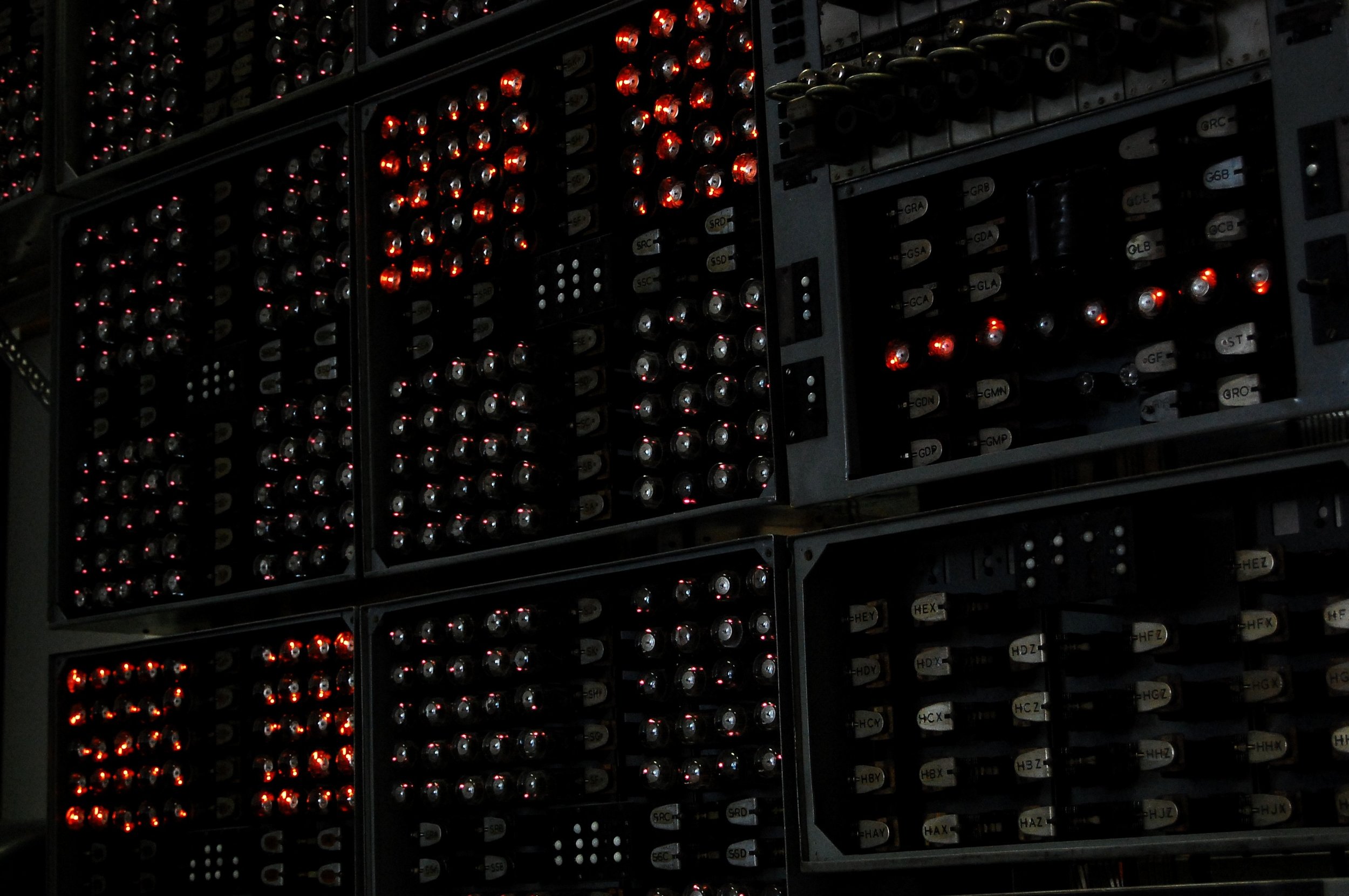
The machine was built using Post Office 3000 type relays, which were at the time a mature and well understood technology. Designed to operate for decades in the harsh environment of a telephone exchange, they were extremely well made. A relay looks deceptively simple, but requires accurate adjustment to operate reliably. We were fortunate to have an expert on the team, who spent the best part of two years cleaning and adjusting every relay set in the machine.
The relays are helpfully identified using two or three letter designations – the first letter indicates the relay set and the remainder in many cases have some mnemonic significance: for example GST is the arithmetic start relay, relay set O is connected with obeying orders and relay set P with print out. This makes it much easier to understand the operation of the machine.
The long and tedious job of relay adjustment has been rewarded by relatively trouble-free operation of the complex relay logic of the machine. We anticipate the ongoing need for periodic cleaning and adjustment of the relay sets.

Mechanical
The machine relies on a number of mechanical contraptions for input and output. Program and data input is via a set of five paper tape readers, of unknown manufacture. If you recognise them, please let us know!
The tape readers are extremely primitive and slow, reading at roughly 5 cps. The tape is advanced one row at a time by means of a solenoid and the five possible holes are sensed by a set of pins pushing against the tape. As a result they easily damage paper tape and it was necessary to use linen rather than paper tape for any program or data that needed to pass through the readers more than a few dozen times.
A further two readers are used on the dedicated editing table. This allows tapes to be merged, split and copied, and operates independently of the rest of the machine, although its controlling relays reside on the main relay rack.
The majority of the tape readers only required minor adjustments and cleaning to bring them back to life, although one has at some point lost a spring. We will require a new part to be fabricated.
The output equipment consists of a Creed 7B printer, a Creed 75 teleprinter and a Creed 7TR re-perforator. All of these were specially modified at Harwell to operate with this machine. The printer, dating from 1944, is actually older than the machine.
There is also a Creed 7P perforator, used to create program and data tapes.
The standard Creed models used serial I/O – a more primitive version of the RS-232 serial port which until recently could be found on every modern PC. By contrast this machine uses parallel 5-wire I/O. There are standard 5-bit character codes, but in common with many other early computers this machine used a custom character set. One reason for this was to simplify the logic required to assure correct operation – thus the numbers 0-9 that form the instruction code are all represented by combinations of two holes, and the block marking codes used to delineate program or data sections by combinations of three holes. This meant relatively simple logic could detect when an unexpected code was encountered and halt operation.
Restoration of these machines involved nothing more than a good clean and some adjustments – they really were built to last! Again we are fortunate to have experts in this technology at the museum who were able to carry out the work.

Electronics
Sequence control is entirely relay based, but arithmetic is all electronic, built using valves, trigger tubes and Dekatrons. There are also two high voltage power supply units – the rectifier unit converts the AC mains into several high DC voltages, and the stabiliser unit generates about a dozen precise voltages for use in the various circuits.
The rectifier unit has been extensively modified during the operational life of the machine, and now sports a variety of rectification technologies dating from the 1950s (copper oxide) to the present day (silicon diodes). We had to replace some of the original copper oxide rectifiers with modern components, but others had already been replaced during the machine's time at Wolverhampton. The other major problem in this unit was a leaking oil-filled transformer, eventually solved by copious use of Araldite. All the transformers in the machine were tested to ensure that the insulation was still in good condition.
Once the power supplies were operating reliably we turned our attention to the pulse generator, which is one of the most complex parts of the machine. Its main job is to generate various sequences of pulses to step the Dekatrons, but also has a hand in starting arithmetic operations, deciding when they are complete, and controlling the transfer and carry units which perform the actual addition and subtraction operations. Some of the subtler (and undocumented) aspects of its operation only became clear when it was back on the racks and interacting with the rest of the machine.
The majority of the work was done with the pulse generator on the bench, with a few switches connected up to provide control inputs. We found around half a dozen failed components – mainly diodes and capacitors. The other major issue was the high speed trigger tubes which start and stop the Dekatron used in the pulse generator to count out ten pulses. We had a large supply of spare tubes which came with the machine, but the majority turned out not to work. Fortunately, we found a supplier who allowed us to test their entire stock of several hundred, but this only yielded a small number of working ones, and some of these no longer work. The most likely explanation is that the gas has escaped around where the pins enter the base – this is surprising since the problem of making valves reliably gas-tight had been largely solved by the early 1950s. Keeping the machine running long-term will eventually require a modification of these circuits to use a more reliable type of trigger tube.
The remainder of the units in the arithmetic rack were repaired one at a time on the bench with the help of the pulse generator and power supplies. These consist of the two halves of the accumulator, which also contain plug-in transfer and carry modules, and the translator unit which converts between 5-wire code and Dekatron compatible pulse trains. The translator is used both when reading numbers from tape into store and when printing out from store. No major issues were found with any of these units bar a handful of failed components.
With the arithmetic rack completed we turned our attention to the stores – nine boxes each containing 80 Dekatrons and associated components. The first two stores built for the machine have a slightly different (and undocumented) design – they can be recognised by the extra relays, including the infamous SEX relay which caused much amusement to generations of visiting school children at Wolverhampton.
When we embarked on the restoration nobody knew how reliable the early types of Dekatron used in the machine would prove to be. The majority are helium-filled Ericsson GC10A, which had a very short production life before being replaced by the much brighter neon filled GC10B. Consequently GC10As are now extremely rare, and the machine almost certainly contains the bulk of those that survive today.
In the event we are pleased to report that sixty year old Dekatrons still work very well! Although they are gas filled like the problematic trigger tubes, we didn't find a single one that had lost its neon or helium fill. This was a major boost to the project and made us confident that it would be possible to restore the machine back to full working order.
The only major problem that Dekatrons suffer from is contamination of adjacent electrodes due to the glow being left in one place for a long period of time. This results in 'sticky' operation – either the glow won't reliably step past a particular cathode, or jumps straight over it. Both of these problems cause an incorrect answer. Luckily the process can be reversed simply by allowing the Dekatron to 'spin' for a long enough period.
To speed up the spinning process we constructed a circuit to boost the output from the pulse generator so that it could drive an entire store's worth of Dekatrons at once. Even so, it took several months to complete the process on every store.
The other somewhat unexpected problem with the store modules was failure of the wirewound resistors associated with each Dekatron. This type of component wouldn't normally be unreliable, but to date we have needed to replace approximately 10% of the 810 resistors. Fortunately we had access to a large quantity of almost identical components, so the replacements have not unduly altered the character of the stores. Many of these resistors failed during the first few days of operation of the restored machine, but thankfully the failure rate has since rapidly dropped off.

Putting it all together
Some of the most interesting problems arose when we put the whole machine back together. We found a variety of short and open circuits in the wiring, some of which proved very difficult to trace. Some of the wiring had been cut in order to separate the racks when the machine was put into storage, and this had to be replaced.
Once all the obvious wiring faults had been cured we were able to perform simple arithmetic operations with reasonable reliability, and read numbers into store. The first proper program to run was a three-instruction loop to clear all the stores to zero.
We were left with various intermittent problems, several of which turned out to require minor design changes to cure. To take an example: multiplication was frequently producing the wrong answer because one of the steps in the arithmetic sequence was being skipped. The problem was eventually traced to the pulse generator, but there was nothing obviously wrong with the circuit components. The resistance or capacitance of very old components can change by quite a large amount. In some cases the changes cancel out and don't affect circuit operation, but sometimes it does cause a problem. In this particular case, the relevant components were all very close to their nominal values, yet the circuit didn't work. Eventually the fault was cured by doubling the value of one capacitor. Another fault with similar symptoms affecting division required a component of five times the original value for the circuit to operate with adequate margin!
No detailed operational log of the machine survives, but it's likely some of these faults have been present for many years and were probably partly responsible for the unreliability which we know the machine developed in its later life. These circuits must only just have worked when the machine was new, and hence even small component value changes caused a problem.
The goal of the restoration was to have the machine fully working and as reliable as when new. By November 2012 this had largely been achieved. Thanks must go to all the restoration team and other experts at the museum who have helped to bring this venerable machine back to life.
In 2013 the Harwell Dekatron / WITCH computer was recognised by Guinness World Records as the world's oldest original working digital computer. This is the second time it has held this record, it previously had it prior to it being switched off in 1973.
Project Team

Delwyn Holroyd has worked in the computer industry for 20 years and has a degree in electronic engineering. His early career was in the mainframe division at ICL, before moving into the fields of non-linear editing and compositing for television and feature film. He is now technical director and co-founder of a company manufacturing digital recording equipment for professional cinematography cameras.
Delwyn became a volunteer at TNMOC in 2009. He has been closely involved in the restoration of the electronics in the Harwell Dekatron computer and is also leader of the ICL 2966 and Cray Y-MP EL restoration projects at TNMOC. His other activities in the field of computer history include a Sinclair ZX Spectrum emulator for mobile phones and, in conjunction with David Holdsworth, an emulator for ICL's George 3 operating system.
Johan Iversen has worked in the computer industry for more than 30 years and has a degree in electronics and computing. His early career was in the Customer Engineering Division (CED) at ICL repairing mini-computers, namely the System Ten (the forerunner to the System25), before moving into Software Development.
Johan became a volunteer at TNMOC in 2008. He has been closely involved in the restoration of the electronics in the Harwell Dekatron computer and he is also leader of the System 25 restoration project at TNMOC.


Eddie Washington worked in the telecommunications industry for 30 years, joining the GPO (the then combined postal and telecomunications provider in the UK) in 1966 as a Trainee Technician Apprentice. He went on to become a maintenance engineer looking after electro-mechanical telephone exchanges in North London and ended his career in BT as an Executive Engineer.
Eddie became a volunteer at TNMOC in 2009 after hearing through the BT grapevine that an organisation on Bletchley Park urgently needed High Speed Relays – three boxes of which he just happened to have in his loft. His first role was in assisting the Tunny group with the adjustments and timings of the Post Office 3000 type relays and Uniselectors during the final commissioning stages of the Tunny Machine. He was then asked to join the newly forming WITCH Restoration Team in September 2009.
Tony Frazer became interested in electronics at junior school, where he earned extra pocket money by fixing germanium transistor radios. He started the school's Electronics Club and became interested in building electronic gadgets.
Tony became involved in computing in 1980, writing BASIC programs (and playing games like STTR1, KINGDM, OXO) on a Data Dynamics 390 teleprinter connected by acoustic coupler to the Open University Computing Service in Newcastle-upon-Tyne. He studied Chemistry, but his first job was developing and running software for the finance department of a bank. In the 1990s, he "defected" from the ranks of mainframe developer having seen VB3 running on a PC. He went on to develop a graphical Time Management system in his spare time, which got him started developing front ends for Access and Oracle databases. He now works as a database developer doing 'stuff' in Oracle and SQL Server.