
Marconi TAC - Transistorised Automatic Computer
Designed in 1959/60 at Marconi's R&D Department at Great Baddow, near Chelmsford, this is one of the more unusual systems we have on display. Contained within four large cabinets and a control desk, it was one of the first transistorised computers made in the UK. Ours was used as a monitoring system for a nuclear power station. It gave sterling service from its installation in the mid 1960s to finally being decommissioned in 2004 - that's almost 40 years! That is amazing considering the technology being used. It was kindly donated to the museum.

The Marconi Tac display at the museum
The Marconi Transistorised Automatic Computer (“TAC”).
The Marconi TAC is a second-generation computer based on germanium alloy junction transistor technology. It was designed in 1959 - 1960 in response to a requirement for a computer to be used for real-time processing of RADAR information for an early warning system for the Swedish government. Later, two more were made for use at the Nuclear Power Station at Wylfa in North Wales.
As far as we know, only five of this type of computer was ever produced and only the two from Wylfa survive. One is in TNMoC and the other is in the Jim Austin private computer collection near York.
TNMoC's Marconi TAC
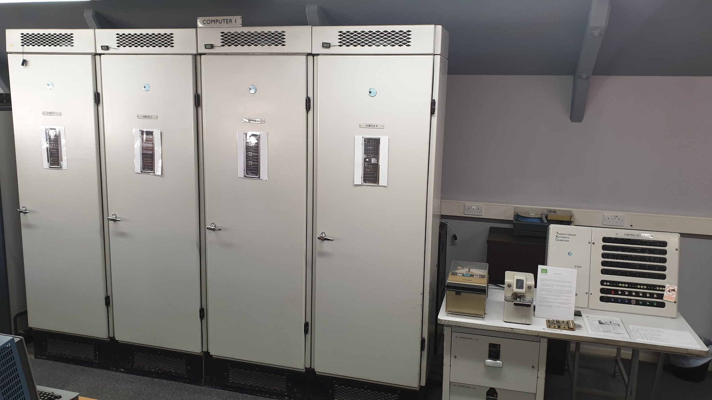
The TAC consists of four Cubicles and a control desk.
Cubicle 1 contains the magnetic core memory (two banks of 2k x 20 bits) and driver circuits and the Master Clock. The Master Clock actually consists of two interleaved 500kHz clocks – each instruction starts on an A clock pulse and ends on a B clock pulse.
Cubicle 2 can be considered as the CPU as it contains the ALU (Arithmetic Logic Unit) plus the Registers.
Cubicle 3 contains the hardware Microprogam – this consists of many diode matrix boards which implement complex instructions such as trigonometric functions.
Cubicle 4 contains the majority of the DC Power Supplies plus the Input/Output circuitry.

The Control Desk has an Operator Panel plus, hidden behind a cover, an Engineer's Panel. The two drawers in the desk contain the Control Logic for the Paper Tape Reader and Punch.
When the TAC was in situ at Wylfa, it was connected to a Magnetic Drum Store which was shared with the second TAC. The drum was later found to be unreliable and replaced with a shared Magnetic Core Store. There was also an Analogue to Digital converter to convert the thermocouple temperature signals and a “Turbine Run Up” rack that interfaced with the turbine control gear. Unfortunately, we didn't receive any of this ancillary equipment (although we have masses of spare parts for them!).
Timeline
The Marconi TAC (Transistorised Automatic Computer) was designed in response to a 1958 Request for Proposal from the Swedish Government for a computer-controlled Early-Warning System (later code-named “Fur Hat”).The RFP addressed concern over the Soviet Union's “sabre-rattling” during the Cold War. The Soviets were sending nuclear-armed bombers to probe the defences of the Western Governments. The “Fur Hat” system would detect these bombers using RADAR and would be able to track them in realtime and predict when they would be expected to cross into the airspace of Western countries so the countries could send up interceptor jets to warn them off. Marconi decided to tender for the contract for the complete system, but they had no suitable computer in their product portfolio. So the job of designing a suitable computer was given to the Marconi Research and Development department, based at Great Baddow, near Chelmsford in Essex.
Marconi Great Baddow site in 1960s

The task of designing the computer was given to a young man by the name of Digby Worthy. Mr. Worthy was described by his peers as “a personable young man”. The Swedish report on the project describes him (roughly translated, with the help of Google Translate):
“Digby Worthy was the overall developer of the TAC computer, Marconi's first transistor computer. He created the architecture behind the mathematical calculation of the computer and is considered an important personality, great talent and pioneer within his field.”
Bernard de Neumann says: “I remember Digby Worthy very well - he was famous at Oxford Uni for discovering that the introduction of a small quantity of condensed milk into a bicycle tyre inner tube made it self-sealing in the event of a puncture! No one could quite imagine how he made this singularly practical discovery! His reports on TAC and programming always made interesting reading. He was always an interesting bloke to talk to with interesting ideas...”
Many of Digby's reports on TAC design and development were co-authored by a young lady called Miss Moira J Woodhead. They must have been working very closely together because, from the Spring of 1960, document references to her change to Mrs. M.J. Worthy.
The three TACs used in the Fur Hat system were installed in 1962 and the system was fully operational by 1964. It is generally accepted that the Fur Hat system was around 10 years ahead of any similar system in the world.
Cartoon of Fur Hat System

Two additional TACs were part-built as spares for the TACs in the Fur Hat system, just in case anything went awry such as the three TACs lacking in power. By 1965, the decision was made that the two spare systems would not be needed, so clearance was given that they could be sold.
As luck would have it, the CEGB (Central Electricity Generating Board) were in the process of building a new Nuclear Power Station at Wylfa, on the island of Anglesey in North Wales. They had decided that this new Power Station would use computers to monitor and manage any alarms that were generated by the Nuclear Reactors and their cooling systems etc.In 1966, Marconi offered two TAC machines running in a “High Availability Pair” configuration for this task, and the offer was accepted.
Wylfa Nuclear Power Station

The two TACs were operational in 1967, the Power Station went to 24-hour generation in 1968 and the TACs ran non-stop from then until their switch off in 2004. The TACs were replaced in stages over several years by a combination of DEC (Digital Equipment Corporation) PDP11 and Alpha computers.
Wylfa finally finished generation in December 2016 and is now in the decommissioning phase. We (TNMoC) have been in communication with the decommissioning company and hope that we will be invited to visit to see if there is any more documentation, spare parts, peripherals etc. that we can use to enhance the TAC display.
Technology
At the time of TAC's inception, Germanium alloy junction transistors were quite common, but Germanium micro-alloy and particularly Silicon transistors were new and expensive. The table below compares the amount of draught beer you could buy in 1964 (at 1s 10d a pint) for the price of each transistor. Remember that a typical working man was only taking home around £10 per week in wages at that time.
Transistor Price Comparison
Transistor Type
Price in 1964
UK Beer Equivalence
Germanium Alloy Junction (OC42m)
£0 7s. 0d.
3.5 pints
Germanium Micro-Alloy Junction (Dat1A, Dat2)
£1 13s. 6d.
17 pints
Silicon (2N1257)
£6 4s 0d
68 pints
Hence the TAC utilises a mix of different types of transistors – germanium micro-alloy and silicon are used where their speed and reliability are required and germanium alloy junction are used everywhere else to keep the overall price down.
There is an additional cost involved in using different types of transistor because they typically run from different voltage rails – so the TAC runs rails for -5V, +10V, -10V and -20V. Further, because the (linear) DC power supply modules in TAC use germanium power transistors (the ubiquitous 2N3055 silicon power transistor wasn't available yet!), they play safe with the risks of thermal runaway and use lots of small power supply modules . Indeed, there are a total of 40 power supply modules in the TAC, each of which is rated up to 2A load current.
The basic logic of the TAC is Diode Transistor Logic (DTL) where the transistor is the switching element and all the inputs are presented through diodes. The early prototype TAC used all plug-in modules, but the edge connects were found to be unreliable so were replaced with soldered-in modules. The photograph shows a Fast Basic Logic Module using germanium micro-alloy transistors.

The PCB has been removed from its black plastic cover so you can see it clearly. Note:
- the flying leads (no edge connector);
- the mass of input diodes on a small daughter board;
- the five germanium micro-alloy transistors (gold-coloured).
This particular board is a “5NF5” module which decodes as:
- 5 gates;
- N-type (can be used for various types of gates);
- Fast logic (i.e. germanium micro-alloy);
- 5 inputs per gate (hence the total of 25 diodes – some of these have been replaced with a different type on this board, so some are black and some are white).
The design of the TAC was unusual for the time because it is a microprogrammed machine with a complex customisable Instruction Set (or Order Code, as they called it then). This meant that complex mathematical functions such as sine, tangent etc. could be included in the native Instruction Set and hence processed at high speed with very little RAM utilization.The microprogram is stored in a series of diode matrix boards – the ROM technology of the time.
A Diode Matrix Board (unloaded)

Displaying the Marconi TAC
When we received the TAC it came with only four peripherals:
- The switches on the Console (input only)
- The lamps on the Console (output only)
- The Paper Tape reader (input only)
- The Paper Tape Punch (output on ly)
This makes it difficult to provide an interactive display to museum visitors. This is further complicated by the fact that the TAC has no serial interface and only a complex non-standard parallel interface. To solve this problem an interface adapter unit is in development. This will allow connection between the TAC and modern computer interfaces such as USB. When this interface adapter is available, we envision that the TAC will be connected to a touch screen computer which will simulate a Nuclear Power Station - thus allowing the TAC to be displayed performing the same tasks as it did during its long working life.
Interface Adapter in development

[Steve Kay BA(Hons), PGDCCI, MIEEE. Computer Field Service Engineer and Manager (7 years), Network Management (9 years), Freelance Network Consultant (10 years), Principal Test Engineer on Network Security Products (14 years). Now retired and volunteering at TNMoC.]