

10 - Bombe Description
A Bombe consisted of three electrically isolated but mechanically connected banks of drums. Each vertical set of three drums was equivalent to an Enigma and there were 36 of these in total. The 26 wires leading into each such Enigma and the 26 wires leading from them were taken out to the Enigma columns on the gate at the rear of the machine.
The Bombe was designed to look for open circuits, a purely electrical phenomenon. If an open circuit occurred then the letter which had that open circuit was interpreted as the potential stecker of the input letter, i.e., the letter to which the sense relays and the test switches were plugged.
There were two conditions in which there could be open circuits at the sense relays. The first was when the test letter chosen (i.e., the source of electric current) was incorrect and the current from that letter was able to get to 24 other letters but not to the 25th, which would have been an open circuit and would be indicated by a single relay.
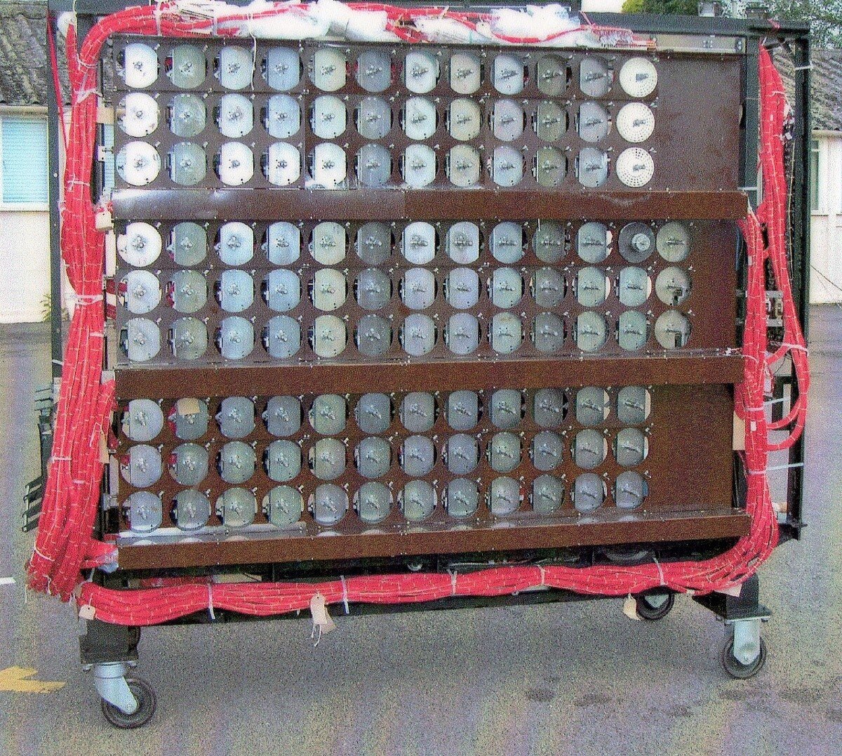
Figure 9 - The Bombe rebuild under construction: note the extensive wiring
The second was when the test letter was correct and current could not get to any other letter, in which case 25 relays would be indicated. The potential stecker being the one not indicated. The test of 26 possible steckers is made at each position of the drums, which are advanced through 17,576 positions in each run.
Relay Gate
This gate, on the back of the Bombe, has 104 sense relays arranged in chains of 26. They can detect an open circuit on the input letter of the menu leading to a stop. The 26 stop-and-cancel relays record the position of the fast drums where a stop is detected and bring the machine back to this position after the drums have slowed down. The multi-relays then transfer the state of the sense relays to the indicator. Also located on the gate are the running circuit relays and associated resistors which control all the functions of the machine.
Diagonal Board
The diagonal board is made up of 26 jacks of 26 contacts each, representing all possible steckering of each letter to itself and each other letter. The diagonal board is wired up as a square matrix in columns 1, 4 and 7 of the gate with 338 wires (13x26) per column soldered on to jack contacts at each end. These connections are permanently wired, i.e., if ‘A’ is connected to ‘f’ then ‘F’ is connected to ‘a’.
Commons
These columns consist of four or five jacks connected in parallel and are necessary when many cables need to be connected to the same point in the menu.

Figure 10 Left to right: Diagonal Board, Commons and Enigmas plugged up on the Bombe
‘Enigma’ connections
Three of the nine columns of jacks are connections to the ‘Enigmas’ (the 36 sets of three drums). There are 12 input and output pairs on each column. Menu cables are then plugged into each Enigma according to the menu. To reduce the number of connections, special ‘cross-and-connect’ units are available which take the output of one Enigma and connect it directly to the Enigma below, with an additional jack incorporated into it that allows a further connection.
Horizontal Shafts
These drive the upper drums through the worm and worm-wheel gears. Each is driven through a bevel gear from the main vertical drive shaft.
Carry Bars
There are six of these and they are selected to progress the middle and lower drums. Middle drums carry once every one and a half revolutions of the top drums. The lower drums carry once for every revolution of the middle drums.
Sense Relays
The sense relays – of which there are three sets available – are connected to the input letter of the menu by 26-way cables. At each of up to 17,576 positions a test is applied that requires further analysis. To detect a stop the Bombe looks for only one, namely that there is at least one sense relay to which current does not get back.
Reflector D
In January 1944, Luftwaffe traffic introduced a second reflector known as ‘Uncle D’ for ‘Dora’ at Bletchley Park. Unlike the standard Reflector B, which was fixed, the new reflector was pluggable, but fortunately the Germans introduced it piecemeal along with the existing Reflector B. What was seen as a possible move that could have put the Bombe out of business was quickly overcome.
In Norway, the Germans used Reflector D with the same stecker, wheel order and ringstellung as those networks using Reflector B and within 24 hours Bletchley Park had found the D wiring. It was discovered that D was pluggable and seven different wirings of D were found, but in all of them B was paired with O. The wiring consisted of 13 pairs of letters, i.e.: A/Y, B/O, C/L, D/J.
On the Bombe, reflectors are implemented as plug boards on the left-hand end of the machine. Reflector B plugboards were generally left in situ, but for Reflector D work other plugboards were wired as needed. One end of a plug would be inserted in A and the other reversed and plugged into Y etc. Three banks were plugged in the same way.
Double-ended scrambler
The Enigmas on the Bombe needed to be double-ended to provide separate input and output access to enable continuous circuits through several scramblers coupled together in series and in either direction. Scramblers were connected in series, for example:
connect scrambler A to B
connect scrambler B to G
without directly connecting A to G. Single-ended scramblers cannot do this.
To enable drums to be double-ended, each drum had two sets of internal wiring which matched the internal wiring of its corresponding Enigma wheel. The wiring in the drums bridged the contacts of the OUTER and THIRD rings and the INNER and SECOND rings. Each double-ended scrambler was symmetrical – if R was input at the left end of the scrambler which resulted in F being output at the right end, then if R was input at the right end, F would output at the left end. These interconnections are the same as those between the right and left-hand rings of Enigma wheel terminals.
(c) John Jackson